Transistor Schematic

Transistor schematic
The schematic symbols used to represent field effect transistors are marked with the letters of “D”, “G” and “S” corresponding to the terminals of Drain, Gate and Source respectively. The two main types of field effect transistors are: Junction FET's or JFETs, and Insulated Gate FET's or IGFETs.
What is the structure of transistor?
A transistor is an electronic component that is used in circuits to either amplify or switch electrical signals or power, allowing it to be used in a wide array of electronic devices. A transistor consists of two PN diodes connected back to back. It has three terminals namely emitter, base and collector.
How do transistors work?
A transistor works when the electrons and the holes start moving across the two junctions between the n-type and p-type silicon. The small current that we turn on at the base makes a big current flow between the emitter and the collector.
What are the 3 circuits of a typical transistor?
The three different transistor circuit configurations are: common emitter, common base and common collector (emitter follower), these three circuit configurations have different characteristics and one type will be chosen for a circuit dependent upon what is required.
What is the unit of transistor?
The standard units of a transistor for electrical measurement are Ampere (A), Volt (V), and Ohm (Ω), respectively.
Why is transistor used?
transistor, semiconductor device for amplifying, controlling, and generating electrical signals. Transistors are the active components of integrated circuits, or “microchips,” which often contain billions of these minuscule devices etched into their shiny surfaces.
What are the 2 types of transistor?
Transistors typically fall into two main types depending on their construction. These two types are bipolar junction transistors (BJT) and Field Effect Transistors (FET).
What is type of transistor?
Transistors are broadly divided into three types: bipolar transistors (bipolar junction transistors: BJTs), field-effect transistors (FETs), and insulated-gate bipolar transistors (IGBTs).
What is NPN and PNP transistor?
PNP switches On by a low signal whereas NPN switches ON by a high signal. As we are aware that in PNP transistor, the P represents the polarity of the emitter terminal and N represents the polarity of the base terminal.
What are the two main uses of a transistor?
The core use of transistors includes switching applications or both amplification and switching.
What is a transistor in simple words?
Definition of transistor 1 : a solid-state electronic device that is used to control the flow of electricity in electronic equipment and usually consists of a small block of a semiconductor (such as germanium) with at least three electrodes. 2 : a transistorized radio.
How do you test a transistor?
Connect the base terminal of the transistor to the terminal marked positive (usually coloured red) on the multimeter. Connect the terminal marked negative or common (usually coloured black) to the collector and measure the resistance. It should read open circuit (there should be a deflection for a PNP transistor).
What are NPN used for?
This component is used in amplifying circuits. To amplify weak signals, it's used in Darlington pair circuits. NPN transistors are used in applications where a current sink is required. Some classic amplifier circuits, such as 'push-pull' amplifier circuits, make use of this component.
Why NPN transistor is mostly used?
Generally the NPN transistor is the most used type of bipolar transistors because the mobility of electrons is higher than the mobility of holes. The NPN transistor has three terminals – emitter, base and collector. The NPN transistor is mostly used for amplifying and switching the signals.
Why does a transistor have 3 wires?
The transistor has three legs, these are the base, collector and the emitter. The emitter is always connected to 0v and the electronics that is to be switch on is connected between the collector and the positive power supply. The base of the transistor is used to switch current through the collector and emitter.
What is inside a transistor?
Most transistors are made from very pure silicon, and some from germanium, but certain other semiconductor materials are sometimes used. A transistor may have only one kind of charge carrier, in a field-effect transistor, or may have two kinds of charge carriers in bipolar junction transistor devices.
How do you power a transistor?
Operation of Power Transistor Case 1: Power transistor base is connected to the negative terminal and the positive terminal is connected to the emitter. Case 2: The collector is connected to the negative terminal and the positive terminal is connected to the base terminal of the transistor.
What is transistor why it is so called?
The word transistor is a combination of transfer and resistance. This is because it transfers the resistance from one end of the device to the other end or we can say, transfer of resistance. Hence, the name transistor. Transistors have very high input resistance and very low output resistance.
Why do transistors need a resistor?
The resistors are used as a means of generating voltage drops and thereby pulling the transistor into the desired operating region. because you need to limit the current to semiconductor terminals. otherwise, the transistors will be damaged.
How do you connect a transistor?
To connect the transistor as a switch in a circuit, we connect the output of the device that will switch on the transistor to the base of the transistor. The emitter will connect to ground of the circuit. And the collector will connect to the load that the transistor will turn on and the supply voltage of the circuit.
11 Transistor schematic Images
Insulated Gate Bipolar Transistor IGBT Transistor Transistors

Pin on danny

Transistor series voltage regulator with overload and short circuit

Image result for 2n2222 transistor circuits Transistors Circuit Pics

simple two transistors am transmitter circuit Electronics circuit

5 BAND EQUALIZER CIRCUIT USING TRANSISTOR Saport4ucom in 2020
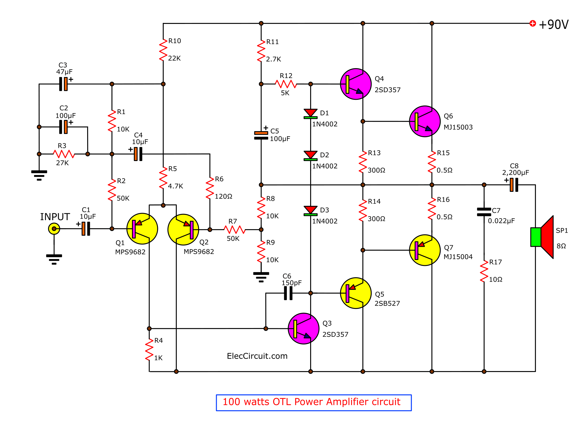
poweramplifierotl100wbytransistormj15003mj15004withpcbjpg

Choccy Block TRF Radio Schematic Diagram Transistor radio Spectrum

Pin on Transistor

Variable Voltage Current Power Supply Circuit Using Transistor 2N3055
Post a Comment for "Transistor Schematic"